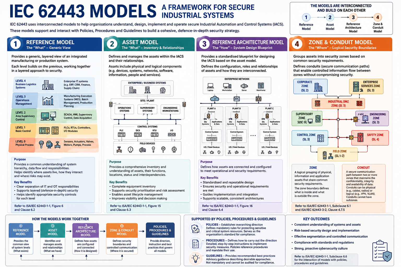
IEC 62443 uses a collection of interconnected models to describe, design and secure Industrial Automation and Control Systems (IACS). Rather than viewing cybersecurity as a collection of independent technical controls, these models provide different perspectives of the same system.
Each model answers a different question and progressively builds towards a secure, well-designed industrial architecture.
Together these models support cybersecurity risk assessments, defence-in-depth, network segmentation, system design and lifecycle management.
The Reference Model provides a generic, technology-independent view of an Industrial Automation and Control System (IACS). It represents a manufacturing or production system as a hierarchy of logical levels.
| Level | Description | Typical Devices |
|---|---|---|
| 4 | Business Logistics — Enterprise IT systems that manage business planning, finance, inventory, order fulfillment and supply chain. These systems set production schedules and commercial priorities for the plant, but do not directly control process equipment. | ERP, Finance, Supply Chain |
| 3 | Operations Management — Site or plant-level systems that manage production workflows, work orders, quality, material tracking and historical data. They coordinate manufacturing operations and translate business plans into actionable production instructions for lower levels. | MES, Historians, Batch Systems |
| 2 | Area Supervisory Control — Supervisory systems that monitor and control process areas or manufacturing cells. Operators use these systems to visualise process status, issue setpoints and commands, acknowledge alarms and supervise automated control at Level 1. | SCADA, HMI, DCS |
| 1 | Basic Control — Real-time controllers that execute continuous, sequential or discrete control logic. These devices read process measurements, run control algorithms and drive final control elements to keep the process within the required operating envelope. | PLC, RTU, Controllers |
| 0 | Physical Process — The actual industrial process and the field devices that interface with it. Sensors measure physical variables; actuators, valves and motors manipulate the process. This level is where cyber-physical effects become visible in the plant. | Sensors, Valves, Actuators, Motors |
Reference: ISA/IEC 62443-1-1, Clause 6.2
The Asset Model describes the hierarchical relationships between assets within an Industrial Automation and Control System (IACS). Where the Reference Model describes functional levels of an industrial system, the Asset Model identifies the assets that exist at each organisational or physical level and how those assets nest within one another.
Assets may be physical (such as controllers, field devices and plant equipment) or logical (such as software applications and network services). Understanding these relationships is foundational for inventory, risk assessment, architecture design and later zone definition.
| Asset Level | Description |
|---|---|
| Enterprise | The top of the hierarchy. Represents the overall organisation that owns or operates one or more industrial facilities, including corporate business systems and the enterprise-wide management of production assets. |
| Geographic Sites | Physically distinct locations belonging to the enterprise, such as factories, refineries, terminals, substations or remote facilities. Each site typically contains multiple production or operational areas. |
| Area | A major subdivision within a site, often corresponding to a process area, plant section or manufacturing department (for example, utilities, packaging or primary production). Areas group related lines, units or cells. |
| Lines, Units, Cells, Vehicles | The next level of process organisation within an area. These groupings represent identifiable production trains, process units, work cells or mobile assets that perform a defined manufacturing or operational function. |
| Supervisory Control Equipment | Systems used to supervise and coordinate production within lines, units or cells, such as SCADA, HMI and supervisory DCS nodes. Operators interact with the process primarily through this layer. |
| Control Equipment | Basic control assets that execute real-time control logic, including PLCs, RTUs and other controllers. These assets receive measurements, apply control strategies and issue commands to field devices. |
| Field I/O Network | The communications infrastructure that connects controllers to sensors and actuators. This includes fieldbuses, I/O networks and related networking equipment that carry process signals and device data. |
| Sensors and Actuators | Field instrumentation that measures process variables or manipulates the process, including transmitters, switches, valves, drives and similar devices. These assets form the cyber-physical interface between the control system and the plant. |
| Equipment Under Control | The physical process equipment being controlled, such as pumps, compressors, reactors, conveyors, pipelines or other plant machinery. Compromise of higher-level cyber assets can result in unsafe or unintended operation of this equipment. |
By mapping assets into this hierarchy, organisations can define the scope of the IACS, understand containment relationships and identify which assets require protection based on their function and consequence of compromise.
Reference: ISA/IEC 62443-1-1, Clause 6.3
The Reference Architecture Model builds on the Asset Model by showing how assets are configured and interconnected within an Industrial Automation and Control System (IACS). Where the Asset Model identifies assets and their hierarchical relationships, the Reference Architecture describes the practical system arrangement used for design, assessment and security planning.
In IEC 62443-1-1, the reference architecture provides a technology-oriented view of the system. It maps assets onto networks, interfaces and communication paths so that engineers can understand how information and control signals move between enterprise, operations, supervisory, control and field layers.
| Element | Description |
|---|---|
| Asset Configuration | Places identified assets into their operating context, showing which systems, devices and applications exist and how they are grouped across plant areas, process units and functional levels of the Reference Model. |
| Network Topology | Illustrates the communications infrastructure used by the IACS, including plant networks, control networks, fieldbus or I/O networks, demilitarised zones (DMZs) and links to enterprise systems. |
| Communication Paths | Identifies where and how assets exchange data, including process values, setpoints, commands, alarms, engineering downloads and historian traffic. These paths later become candidates for conduit definition. |
| System Interfaces | Defines the interfaces between major systems such as ERP/MES to control systems, SCADA/HMI to controllers, controllers to field devices, and remote access entry points. Interfaces are common trust boundaries and therefore cyber-risk priorities. |
| Hardware and Software Roles | Clarifies the role of each component in the architecture, for example engineering workstations, domain controllers, historians, HMIs, PLCs, RTUs, safety systems and field instruments. Role clarity supports inventory, hardening and access control decisions. |
| Security Boundary Candidates | Highlights natural separation points in the architecture where defence-in-depth controls can be applied. These boundaries form the practical starting point for defining security zones and conduits under Clause 6.5. |
The reference architecture therefore acts as the blueprint for the IACS: it connects the functional view of the Reference Model with the asset hierarchy of the Asset Model, and provides the configuration needed before security zones and conduits are applied.
Where practical, architectural boundaries should align with physical plant boundaries. Aligning architecture with plant layout simplifies operations, administration and the later assignment of security zones.
Reference: ISA/IEC 62443-1-1, Clause 6.4
The Zone and Conduit Model is where cybersecurity design lands on the reference architecture. Assets with the same security needs are collected into security zones; traffic between those zones is forced through conduits where controls can be applied. The teaching idea is simple: protect like-with-like together, and make every trust-boundary crossing explicit — supporting defence-in-depth and limiting how far a compromise can travel.
Think of zones and conduits as a way to draw trust boundaries on the reference architecture. Assets that should be protected together sit in the same zone; traffic that must leave that boundary travels only through a defined conduit where controls can be applied.
A zone can follow physical plant layout, logical network structure, or both. A conduit is not “another process area” — it is the communications grouping that joins zones and carries the channels between them.
A security zone is a set of logical or physical assets that share the same security requirements. Drawing zones helps the organisation treat like assets alike: one policy set, one risk conversation, and one place to put compensating controls when needed.
In teaching terms, zoning is how you make defence-in-depth designable. Segmentation shrinks what an attacker can reach; a clear boundary contains incidents; and risk-based Security Levels can be assigned per zone instead of one blanket level for the whole plant. Controls can also track who operates and owns the assets — useful when safety systems, engineering networks and basic process control sit side by side.
Where a single zone is still too coarse, create subzones. Common patterns are separating safety instrumented systems from basic control, or splitting engineering access from operator HMIs inside the same area.
Zone boundaries are decided by walking the reference architecture and asking which assets belong together under one security posture. Useful grouping prompts include operational role (SCADA versus basic control versus safety), similar consequence if compromised, shared physical location, common trust assumptions on a network or domain, the same operating team or access model, and shared platforms or connectivity patterns.
Treat the first cut as provisional. Risk assessment often splits an early “similar” grouping where exposure, consequence or required protection diverge enough to justify a separate zone.
Documenting a zone is about making it assessable and operable — not filling a checklist for its own sake. In practice, zone records answer a short set of teaching questions:
| What to capture | Why it matters |
|---|---|
| Identity and purpose | Give the zone a unique name and describe what it is for. Anyone reading the architecture should understand the zone’s operational role without guessing. |
| Boundary and contents | State where the trust boundary sits (physical and/or logical) and list the systems, devices, applications and data inside it. Inventory and boundary definition travel together. |
| Policy and access | Record the rules that apply inside the zone and who or what may use its assets — including authentication and authorisation expectations for people and systems. |
| External links and risk context | Note the conduits that connect elsewhere, the threat and trust assumptions used in analysis, the target Security Level for the zone, and which organisation owns day-to-day security accountability. |
That summary replaces a long clause-style inventory: if a zone definition covers identity, boundary, contents, rules, connections, risk posture and ownership, it is complete enough for design, assessment and audit conversations.
A conduit groups the communication channels that must remain trustworthy when zones exchange information. It is the controlled path across a trust boundary — not an open highway between zones.
When you define a conduit, establish four things: which zones talk, what traffic is allowed (data, commands, services), which communication assets carry it (cabling, wireless, routers, firewalls, VPNs, gateways), and which protections apply on that path.
A few modelling habits keep diagrams honest: a zone may use several conduits; a conduit joins two or more zones for permitted traffic; a conduit should not wander across unrelated trust boundaries without stated controls; and conduits stay focused on communications even when zones nest into subzones.
Implementation can be physical, logical, or mixed — plant Ethernet, DCS networks, fieldbus, wireless links and remote-access paths are all common conduit realisations.
Conduit documentation should explain what crosses the boundary and how that crossing is kept safe. Group the record around these teaching themes rather than copying an annex-style list:
| What to capture | Why it matters |
|---|---|
| Identity and connected zones | Name the conduit, state its purpose, and list the zones it joins — including direction of allowed traffic where one-way or restricted flow is intended. |
| How traffic is carried | Identify the communication assets (media, switches, routers, firewalls, VPNs, gateways) and the channels, services and protocols permitted on the path. |
| Controls and protection strength | Record conduit policy (what is allowed or denied, and how traffic is inspected), access and authentication for users or systems that may use the path, technical protections such as firewalling, encryption or monitoring, and the Security Level target justified by the zones and data involved. |
Zones and conduits together turn architecture drawings into segmentable, controllable trust boundaries — the practical basis for industrial defence-in-depth.
Reference: ISA/IEC 62443-1-1, Clause 6.5
Clause 6.6 explains how the IEC 62443 models relate to one another. Each model provides a different perspective of the same IACS, and the value of the framework comes from using them together rather than in isolation.
| Model | Role in the Relationship |
|---|---|
| Reference Model | Establishes a common functional view of the industrial system as Levels 0 to 4. It provides shared terminology for discussing business, operations, supervisory, control and physical process layers. |
| Asset Model | Identifies the assets that exist within the IACS and shows how those assets nest hierarchically from the enterprise down to equipment under control. |
| Reference Architecture | Configures the assets into an interconnected system view, showing networks, interfaces and communication paths used for design and assessment. |
| Zone & Conduit Model | Applies security structure to the architecture by grouping assets into zones with common security requirements and controlling inter-zone communications through conduits. |
In practice, the models are applied in a progressive sequence:
Policies, procedures and guidelines support every stage, ensuring that the models are not only drawn once during design, but used throughout assessment, implementation, operation and maintenance.
Each model builds on the previous one, creating a structured approach to designing, operating and maintaining secure Industrial Automation and Control Systems.
Reference: ISA/IEC 62443-1-1, Clause 6.6