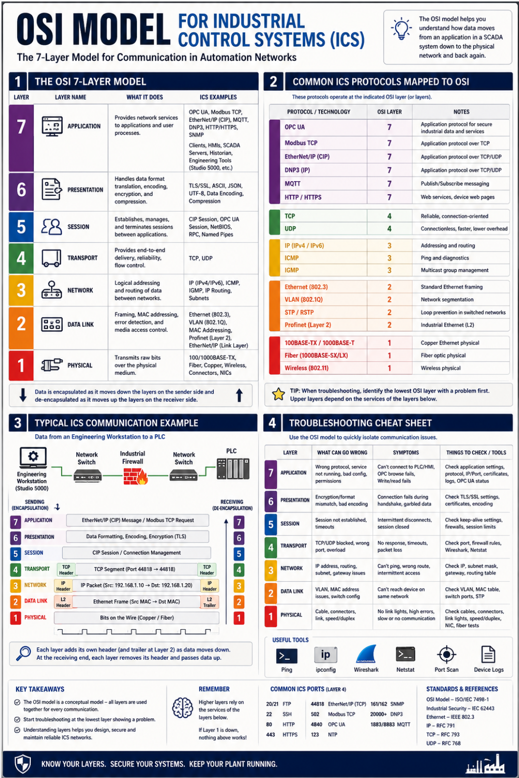
The Open Systems Interconnection (OSI) Model is a seven-layer conceptual framework used to describe how data is communicated between devices on a network.
| Layer | Name | Purpose | Examples |
|---|---|---|---|
| 7 | Application | Provides network services directly to software applications and defines how application data is exchanged between systems. This layer contains the protocols and services used by end-user applications. | CIP, OPC UA, MQTT, Modbus TCP, HTTP |
| 6 | Presentation | Responsible for the representation of data between systems. This includes formatting, encoding, translation, compression and encryption to ensure information can be correctly interpreted by both devices. | ASCII, Unicode, UTF-8, JSON, XML |
| 5 | Session | Establishes, manages and terminates communication sessions between applications. Controls the initiation, maintenance and orderly closure of communications between systems. | Session Establishment, Session Management |
| 4 | Transport | Provides end-to-end delivery of data between devices. Responsible for segmentation, reassembly, flow control, reliability and error recovery during transmission. | TCP, UDP |
| 3 | Network | Provides logical addressing and determines how data is routed between networks. Responsible for forwarding packets from source to destination across one or more interconnected networks. | IP, ICMP, Routers |
| 2 | Data Link | Provides communication between devices on the same local network segment. Responsible for frame delivery, physical addressing, media access control and error detection within a local network. | Ethernet, MAC Addresses, VLANs, Switches |
| 1 | Physical | Defines the physical transmission of bits across a communication medium. Includes the electrical, optical and mechanical characteristics required to transmit and receive signals between devices. | Copper, Fibre Optic, Wireless |
When a device sends data, information is passed down through the OSI layers. Each layer adds information required for communication. The receiving device then processes the information in reverse order.
Application Data
        ↓
Layer 7 - Application
        ↓
Layer 6 - Presentation
        ↓
Layer 5 - Session
        ↓
Layer 4 - TCP / UDP
        ↓
Layer 3 - IP
        ↓
Layer 2 - Ethernet
        ↓
Layer 1 - Physical Medium
This process is commonly referred to as encapsulation and decapsulation.
The OSI Model provides a standard framework for describing and understanding network communications. By separating communication functions into distinct layers, it allows engineers, vendors and organisations to discuss networking technologies using a common language regardless of the specific hardware, software or protocol being used.
The model helps define where technologies operate within a network and how different components interact to move data from one device to another. This standardisation improves interoperability between products from different vendors and provides a structured approach for designing and analysing communications systems.
Although modern networks do not strictly implement every OSI layer, the model remains one of the most widely used frameworks for understanding how networked systems communicate.
Once the role of each technology is understood, the OSI Model can also be used as a structured methodology for troubleshooting communication issues by helping identify which layer is responsible for a particular function.
TCP/IP Fundamentals
The OSI Model provides a framework for understanding network communications. The next step is to understand how modern networks actually implement these communications using the TCP/IP protocol suite.